To Perform logical operation ( Xor,AND, 4:1 multiplexer) using Arduino UNO Controller.
Arduino IDE
Proteous
Step1:Open the Arduino IDE
Step2: Go to file and select new file option
Step3:Type the program
Step4:Go to file and select save option to save the program
Step5:Go to sketch and select verify or compile options
Step6:If no error Hex file will be generated in the temporary folder
Step7:Open the Proteus software
Step8:Go to file select new design and click ok button
Step9:Select component mode and click pick devices from the library
Step10:Type the component name in the keyword to select the components and click ok button
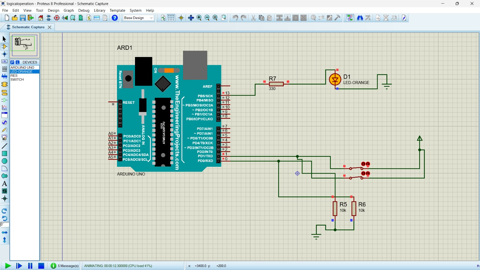
Step11:Design the circuit as per the diagram
Step12:Double click the Arduino controller and upload the hex file generated by Arduino IDE
Step13:Click start button and check the output
A logic gate is a basic building block of a digital circuit that has two inputs and one output. The relationship between the i/p and the o/p is based on a certain logic. These gates are implemented using electronic switches like transistors, diodes. But, in practice, basic logic gates are built using CMOS technology, FETS, and MOSFET(Metal Oxide Semiconductor FET)s. Logic gates are used in microprocessors, microcontrollers, embedded system applications, and in electronic and electrical project circuits. The basic logic gates are categorized into seven: AND, OR, XOR, NAND, NOR, XNOR, and NOT. These logic gates with their logic gate symbols and truth tables are explained below.
Basic Logic Gates Operation Basic Logic Gates Operation What are the 7 Basic Logic Gates? The basic logic gates are classified into seven types: AND gate, OR gate, XOR gate, NAND gate, NOR gate, XNOR gate, and NOT gate. The truth table is used to show the logic gate function. All the logic gates have two inputs except the NOT gate, which has only one input.
When drawing a truth table, the binary values 0 and 1 are used. Every possible combination depends on the number of inputs. If you don’t know about the logic gates and their truth tables and need guidance on them , please go through the following infographic that gives an overview of logic gates with their symbols and truth tables.
Why we use Basic Logic Gates? The basic logic gates are used to perform fundamental logical functions. These are the basic building blocks in the digital ICs (integrated circuits). Most of the logic gates use two binary inputs and generates a single output like 1 or 0. In some electronic circuits, few logic gates are used whereas in some other circuits, microprocessors include millions of logic gates.
The implementation of Logic gates can be done through diodes, transistors, relays, molecules, and optics otherwise different mechanical elements. Because of this reason, basic logic gates are used like electronic circuits.
Binary & Decimal Before talking about the truth tables of logic gates, it is essential to know the background of binary & decimal numbers. We all know the decimal numbers which we utilize in everyday calculations like 0 to 9. This kind of number system includes the base-10. In the same way, binary numbers like 0 and 1 can be utilized to signify decimal numbers wherever the base of the binary numbers is 2.
The significance of using binary numbers here is to signify the switching position otherwise voltage position of a digital component. Here 1 represents the High signal or high voltage whereas “0” specifies low voltage or low signal. Therefore, Boolean algebra was started. After that, each logic gate is discussed separately this contains the logic of the gate, truth table, and its typical symbol.
Types of Logic Gates The different types of logic gates and symbols with truth tables are discussed below.
AND Gate The AND gate is a digital logic gate with ‘n’ i/ps one o/p, which performs logical conjunction based on the combinations of its inputs. The output of this gate is true only when all the inputs are true. When one or more inputs of the AND gate’s i/ps are false, then only the output of the AND gate is false. The symbol and truth table of an AND gate with two inputs is shown below.
OR Gate The OR gate is a digital logic gate with ‘n’ i/ps and one o/p, that performs logical conjunction based on the combinations of its inputs. The output of the OR gate is true only when one or more inputs are true. If all the i/ps of the gate are false, then only the output of the OR gate is false. The symbol and truth table of an OR gate with two inputs is shown below.
NOT Gate The NOT gate is a digital logic gate with one input and one output that operates an inverter operation of the input. The output of the NOT gate is the reverse of the input. When the input of the NOT gate is true then the output will be false and vice versa. The symbol and truth table of a NOT gate with one input is shown below. By using this gate, we can implement NOR and NAND gates
NAND Gate The NAND gate is a digital logic gate with ‘n’ i/ps and one o/p, that performs the operation of the AND gate followed by the operation of the NOT gate.NAND gate is designed by combining the AND and NOT gates. If the input of the NAND gate high, then the output of the gate will be low.The symbol and truth table of the NAND gate with two inputs is shown below.
NOR Gate The NOR gate is a digital logic gate with n inputs and one output, that performs the operation of the OR gate followed by the NOT gate. NOR gate is designed by combining the OR and NOT gate. When any one of the i/ps of the NOR gate is true, then the output of the NOR gate will be false. The symbol and truth table of the NOR gate with the truth table is shown below.
Exclusive-OR Gate The Exclusive-OR gate is a digital logic gate with two inputs and one output. The short form of this gate is Ex-OR. It performs based on the operation of the OR gate. . If any one of the inputs of this gate is high, then the output of the EX-OR gate will be high. The symbol and truth table of the EX-OR are shown below.
Exclusive-NOR Gate The Exclusive-NOR gate is a digital logic gate with two inputs and one output. The short form of this gate is Ex-NOR. It performs based on the operation of the NOR gate. When both the inputs of this gate are high, then the output of the EX-NOR gate will be high. But, if any one of the inputs is high (but not both), then the output will be low. The symbol and truth table of the EX-NOR are shown below.
int bs0 = 0;
int bs1 = 0;
void setup() { pinMode(13, OUTPUT); pinMode(0, INPUT); pinMode(1, INPUT); } void loop() {
bs0 = digitalRead(0); bs1 = digitalRead(1); if (bs0&bs1) { digitalWrite(13, HIGH); } else {
digitalWrite(13, LOW);
} }

Thus the logical operation was performed by Arduino UNO controller