DropBotCase
Table of Contents generated with DocToc

All parts are described in the DropBot case repository, which also contains an `svg` file for each of the laser cut parts. The collection of files can be downloaded by clicking on the latest "snapshot" link.
These parts should be cut from 3mm acrylic.
| Quantity | Description | Image |
|---|---|---|
| 1 | Top |  |
| 1 | Bottom | 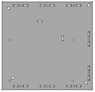 |
| 1 | Front |  |
| 1 | Back |  |
| 1 | Right side |  |
| 1 | Left side |  |
| Quantity | Description | Source |
|---|---|---|
| 21 | Machine screw (M3, .5mm pitch, 16mm) | McMaster-Carr |
| 21 | Thin hex nut (M3, .5mm pitch, 1.8mm height) | McMaster-Carr |
| 4 | Rubber foot (1/4" hole, 1/8" deep) | McMaster-Carr |
Step 1: Assemble the all sides of the case except the front by inserting the tabs in their respective slots
Make sure that the orientation of each of the faces matches that of the picture below.

For each T-slot connection, while holding a nut in the slot with your fingers, use a screwdriver to fasten the joint with a 16mm machine screw (note that the nut should be prevented from spinning by the slot in the acrylic).

