2 Electrical
Note
As a soldering practice and cost cutting effort 💸, some electrical part requires a bit of soldering. If you are new to soldering, need a refresh for soldering, or having any question/concern/problem, please reach out to a MASLAB staff during lab hours for assistance.
For soldering through-hole components, here is a good tutorial video: https://www.youtube.com/watch?v=DJH7VLGJ4fs
For soldering cables together, here is another good tutorial video: https://www.youtube.com/watch?v=NSqPHQ1zQco
The wheel motors come with power and encoder wires. Below is the color code for the motor.

The Red and Black pins are for powering the motor. The other pins are for encoders to count how many revolution has the motor rotated. Raven is designed such that the encoder pins can be plugged directly into one of the encoder ports. The power pins have to be screwed into the motor terminal blocks to provide enough current.
Details for how to connect the motor will be explained later. For now, we need to carefully remove the Red and Black power from the connector housing. To do this, slightly lift the tabs that are keeping the Red and Black wires in place and gently pull those wires out. It is okay if you break the tabs.
Important
When described using relative position (left, right, top, bottom, etc.), the board is assumed to be facing up (component side on top). The 40 pins (20x2) headers is "top". All components are installed on the component side unless mentioned otherwise. Header pins are installed with short side down and long side up.
Warning
Remember to solder the 40-pin header FIRST before anything else! Otherwise, you may be unable to solder it in properly.

Raven is connected to the Raspberry Pi 5 through the standard Raspberry Pi 40 pins connector. It is the 20x2 pins located at the top most edge of the board. To populate it:
- Install the connector such that the exposed pins go from the bottom (side with MASLAB logo) to the top (side with components).

- Make sure the pins are perfectly square with the board and solder the pins. Misaligned pins may not fit on the Pi.
Raven needs a power button to turn on. The connector to this power button is located near top right corner of the 1R0 cube (an inductor). Grab the power button cable, the power button connector, and the power button. Solder the connector, matching the outline on the board. Solder the power button cable to the power button.

Raven uses an XT30 connector at the right most edge to connect to the battery. Install the connector and make sure that the shape of the connector matches the outline (flat edge toward top and angled edge toward bottom of board). Solder the connector.
Caution
As a battery connector, soldering and using this connector incorrectly will likely destroy the Raven board AND the Pi if connected. Please make sure to follow the instruction, take a look at staff's reference board, and ask a MASLAB staff if you are unsure about anything.

Raven uses 5 terminal blocks around the bottom edge to connect to motors. Each terminal block is for one motor. Before soldering the terminal blocks, assemble a row of 5 terminal blocks with the provided blocks. Then insert the row into the through holes. Make sure that the opening points to the edge of the board and solder.

Each motor may be equipped with an encoder. The encoder pins are 4x5 pins located on the left side, above 2 black buttons. Populate Raven's encoder ports with green, blue, yellow, and white headers from left to right.

A typical servo has 3 pins for power and signal. The servo pins are 5x3 pins near the top right corner of the board. Populate Raven's servo ports with black, red, and yellow headers from top to bottom.

Raven also have digital IO ports that are connected to the Pi's GPIOs for buttons / limit switches / digital output. They are 2x5 pins located left of the servo pins. Populate the right column with black headers and left with any color like your team's unique board identifier 😁

The power button you made previously plugs into the power connector. When the battery is connected, this button turns on the system. To turn off, check Raspberry Pi guide.
Raven supports up to 5 motors with 5 optional encoders. If using encoder, make sure the the motor is modified according to Motor.
Each motor terminal block has 2 screw ports for power and ground (GND) for each motor. The left most block is motor 1 and right most block is motor 5.
Each encoder port is made of a row of green, blue, yellow, and white pins. The top most encoder port is for motor 1 and bottom most port is for motor 5. From green to white (or from left to right if you did not use colored header):
(Left to right)
| Green | Blue | Yellow | White |
|---|---|---|---|
| Hall ground | Hall power | C1 | C2 |
To connect the motor power, loosen the screws of a terminal block, insert the power (red) wire into one screw ports and ground (black) wire into the other screw port, and tighten the screws.
Important
The order of the power wires determines if the clockwise rotation is forward or reverse. Feel free to experiment and use whichever order makes the most sense for your software. You encoder value count should match the expected motor spin direction. More specifically, when motor is commanded to go forward, the encoder count should go up and vice versa. If it does not, you will need to swap C1 and C2 to match encoder count direction as well.
To connect the motor encoder, plug the connector with the encoder wires directly onto the encoder pins, matching the colors.
Tip
If you are using the wheel motor you modified in Motor, you can match the colors into the encoder port of corresponding motor. If you are using other motor, check the datasheet and match the signals. They may have slightly different names but they should all have power, ground, and two other signals. Like the motor, reversing the two signal also reverse the encoder count.
Raven supports up to 4 servos. Each servo port is made of a column of black, red, and yellow pins. The left most servo port is for servo 1 and right most port is for servo 4. From black to yellow (or from top to bottom if you did not use colored header):
| Black | Ground |
|---|---|
| Red | Power (5V) |
| Yellow | Signal |
To connect the servo, install the servo connector directly onto the servo pins, matching brown to black, red to red, and orange to yellow.
Raven has 5 digital pins that pair with ground pins. Each digital port is made of a row of your team's favorite colors and ground. The right side of the port is all connected to ground. The left side is as followed from top to bottom:
| Left | Right |
|---|---|
| GPIO6 | GND |
| GPIO16 | GND |
| GPIO5 | GND |
| GPIO7 | GND |
| GPIO19 | GND |
Raven also have 2 qwiic ports to support qwiic devices such as another inertial measurement sensor, color sensor, GPS, and even an LCD. Behind the connectors are connection to the I2C ports of the Raspberry Pi. The left connector is for I2C port 1 and right connector is for I2C port 2. More information about qwiic connection system can be found here: https://www.sparkfun.com/qwiic
Raven uses an XT30 connector to connect to the battery. This is the yellow connector on the right side of the board. It is smaller than the XT60 connector on the battery and requires an adapter.

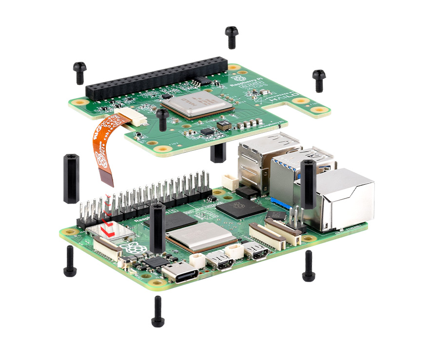
Raven is designed as a compact Raspberry Pi HAT (Hardware Attached on Top) board. It meant to be installed directly on top of the Pi 5. To properly secure the board to the Pi, use 4 sets of M2.5 standoffs, 20 mm threaded spacers, and screws. It should look similar to this without the ribbon cable and M2.5 standoffs in place of the bottom screws:
With the standoffs, you can add holes on your robot to screw the Pi + Raven to the robot, keeping them in place and safe through your robot extreme tasks. Here is a picture of the Pi's layout to help with that:
